null
Toggle menu
Tenergy 48V (13S) 15A Li-ion Battery Protection BMS with Cell Balancing

Tenergy 48V (13S) 15A Li-ion Battery Protection BMS with Cell Balancing

add to cart

Tenergy 48V (13S) 15A Li-ion Battery Protection BMS with Cell Balancing

SKU:
P/N 32206

-

SKU:
32206
Promos/Offers:
Free Shipping

price: $69.99

instant savings: $ 0.00

you pay:$69.99
saved: $0
x

Sales Tax

Tenergy only collects sales tax on orders shipped to addresses in the States of California.

You may be responsible for state and local sales/use taxes when filing your tax returns. Please check your local sales tax laws.

Order now to ship in 1 Business Day

product highlights

  • 13S Lithium-Ion Battery Compatibility: Designed for 13-series lithium-ion and lithium-polymer rechargeable battery packs, featuring a nominal operating voltage of 46.8V and a maximum charging voltage of 54.6V. Suitable for compatible 48V-class battery applications.
  • 15A Continuous Discharge Current: Supports up to 15A continuous discharge current, providing dependable power management for rechargeable battery systems operating within the specified electrical limits.
  • 2.5A Continuous Charging Current: Supports continuous charging currents up to 2.5A, with a specified charging input voltage range of 53.95V to 54.6V for compatible 13S lithium-ion battery packs.
  • Comprehensive Multi-Level Battery Protection: Incorporates overcharge, over-discharge, overcurrent, short-circuit, and temperature protection functions to help prevent battery damage caused by abnormal operating conditions.
 

Product highlights and Specifications:

  • 13S Lithium-Ion Battery Compatibility: Designed for 13-series lithium-ion and lithium-polymer rechargeable battery packs, featuring a nominal operating voltage of 46.8V and a maximum charging voltage of 54.6V. Suitable for compatible 48V-class battery applications.
  • 15A Continuous Discharge Current: Supports up to 15A continuous discharge current, providing dependable power management for rechargeable battery systems operating within the specified electrical limits.
  • 2.5A Continuous Charging Current: Supports continuous charging currents up to 2.5A, with a specified charging input voltage range of 53.95V to 54.6V for compatible 13S lithium-ion battery packs.
  • Comprehensive Multi-Level Battery Protection: Incorporates overcharge, over-discharge, overcurrent, short-circuit, and temperature protection functions to help prevent battery damage caused by abnormal operating conditions.
  • Individual Cell Overcharge Protection: Monitors individual cell voltages and activates overcharge protection at a typical threshold of 4.25V per cell, with automatic recovery when the cell voltage decreases to approximately 4.15V.
  • Individual Cell Over-Discharge Protection: Protects against excessive cell discharge by activating undervoltage protection at approximately 2.70V per cell, with recovery at approximately 3.00V per cell.
  • Automatic Passive Cell Balancing: Features integrated passive cell balancing with a typical balancing current of 42mA, activated at approximately 4.14V per cell when the voltage difference between cells reaches 50mV. Balancing operates during charging or idle conditions.
  • Dual-Level Discharge Overcurrent Protection: Provides two levels of discharge overcurrent detection, with typical protection thresholds of 36.8A and 50A, helping protect the battery system against excessive current demands.
  • Fast Short-Circuit Protection: Incorporates short-circuit protection with a typical detection threshold of 100A and a response delay of approximately 512μs to help minimize damage from electrical short circuits.
  • Advanced Charging Temperature Protection: Includes temperature monitoring to prevent charging under excessively hot or cold conditions, with typical charging protection thresholds of 50°C (122°F) and 0°C (32°F).
  • Discharge and MOSFET Temperature Protection: Features discharge temperature protection with typical thresholds of 70°C (158°F) for high temperature and -20°C (-4°F) for low temperature, plus MOSFET overtemperature protection at approximately 90°C (194°F).
  • Low Power Consumption Design: Features a typical normal-mode current consumption of only 60μA at 25°C, helping reduce the BMS's own power consumption during battery operation.
  • Common-Port Charging and Discharging: Utilizes a shared charging/discharging negative terminal (P−), simplifying battery pack wiring and allowing compatible chargers and loads to connect through the same power port.
  • Compact PCB with Low Internal Resistance: Measures approximately 102 × 55 × 11.5mm (4.02 × 2.17 × 0.45 inches), with a main discharge circuit resistance of ≤30mΩ, supporting integration into appropriately sized battery pack assemblies.
  • Additional Safety and Reliability Features: Includes cell sensing-wire disconnection protection, charging lockout when any cell voltage is at or below 1.5V, and electrostatic discharge (ESD) protection rated at ±4kV contact discharge and ±8kV air discharge. Designed for operation in ambient temperatures from -20°C to 60°C (-4°F to 140°F).
  • Limitation: The BMS does not support digital communication, external discharge-switch control, or series/parallel connection of completed battery packs. It is intended for 13S lithium-ion configurations, and compatibility with battery packs other than the specified design should be confirmed before installation.

Wiring Connection and Installation:
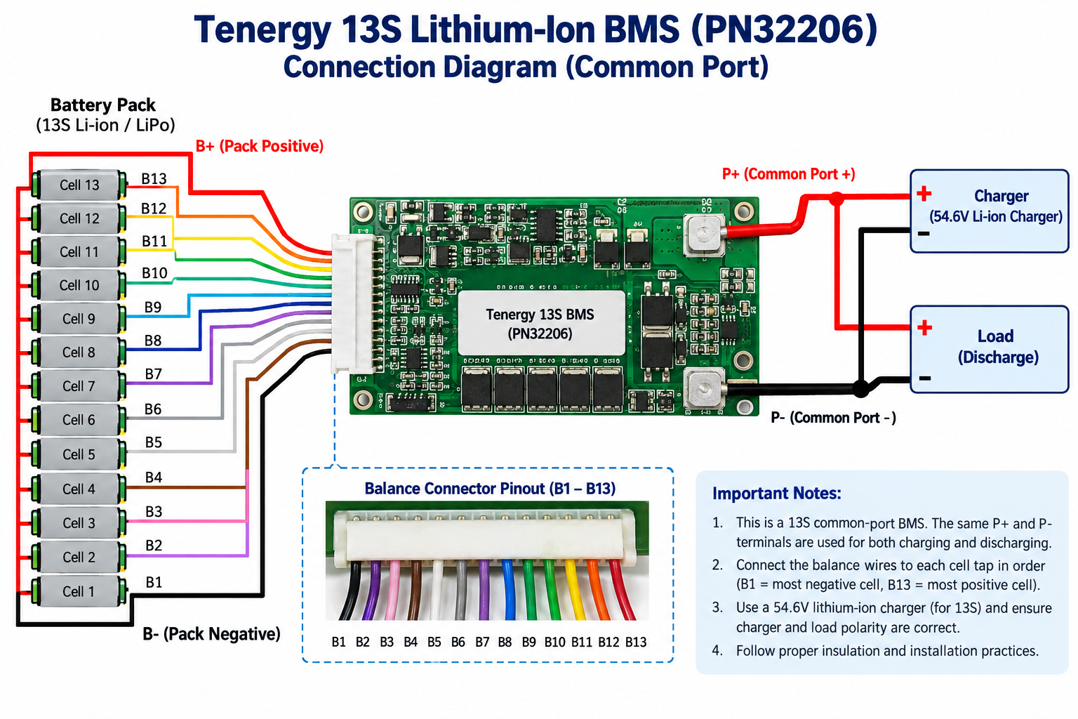
13s-li-ion-bms-connection-diagram.png

Overview

  • The Tenergy PN32206 Battery Management System is designed for 13-series (13S) lithium-ion battery packs. It features a common-port configuration, individual cell voltage monitoring, passive cell balancing, and multiple electrical and temperature protection functions.
  • The BMS requires proper connections to the battery pack terminals, cell voltage sensing wires, and compatible temperature sensors to provide its specified protection functions.

Main Power Connections

Terminal

Description

B+

Battery pack positive terminal; common positive connection for charger and load

B-

Battery pack negative terminal, connected to the BMS B− pad

P-

Common negative terminal for charger and load

The charger and load share the P− connection. The positive terminals of the charger and load connect to the battery pack positive terminal (B+).
Important: B− and P− serve different functions and must not be connected together externally in a way that bypasses the BMS protection circuit.

Cell Voltage Sensing Connections

PN32206 uses two connectors for monitoring the individual cell voltages in a 13S battery pack.

CN2 – 11-Pin Connector (2.0mm Pitch)

Pin

Battery Connection

CN2-11

B− (Pack Negative)

CN2-10

B1

CN2-9

B2

CN2-8

B3

CN2-7

B4

CN2-6

B5

CN2-5

B6

CN2-4

B7

CN2-3

B8

CN2-2

B9

CN2-1

B10


CN1 – 7-Pin Connector (2.0mm Pitch)

Pin

Battery Connection

CN1-7

B11

CN1-6

B12

CN1-5

Not Connected

CN1-4

Not Connected

CN1-3

Not Connected

CN1-2

B+ (Pack Positive)

CN1-1

B+ (Pack Positive)

All cell voltage sensing connections must match the manufacturer's specified pin assignments.

Temperature Sensor Connections

NTC Sensor Requirements:

  • Nominal resistance: 10kΩ ±1% at 25°C
  • B-value: 3435K ±1% (25°C/85°C)
  • Connector: 4-pin, 2.0mm pitch

Temperature sensors should be securely positioned at appropriate monitoring locations within the battery assembly, with proper electrical insulation.

Additional Connectors

  • CN3 – 2-Pin Connector: Reserved for an optional low-current switch function. This function is not required or supported in the specified PN32206 configuration.
  • J1 – Programming Interface: Four-pin programming connection designated for manufacturer programming and servicing. Not intended as a general-purpose communication interface.

Installation Precautions

  • Confirm that the battery pack uses a compatible 13S lithium-ion configuration.
  • Verify all terminal assignments and sensing-wire connections against the manufacturer's specification before applying power.
  • Prevent reversed polarity, crossed sensing wires, and accidental short circuits.
  • Ensure the PCB is securely mounted and electrically insulated from battery cells and conductive surfaces.
  • Use compatible NTC sensors and verify the temperature monitoring configuration.
  • Use a compatible 54.6V lithium-ion charger with charging current limited to 2.5A.
  • Do not exceed the specified 15A continuous discharge current.
  • Protect the BMS from water, condensation, excessive humidity, and electrostatic discharge.
  • Do not modify the PCB, components, or protection circuitry.
  • Before placing the assembled battery pack into service, verify correct charging, discharging, and protection operation.


Professional Installation Required: This BMS is intended for qualified battery pack assemblers and technicians familiar with lithium-ion battery safety. Incorrect installation can cause battery damage, electrical hazards, fire, or personal injury.

Compatibility Note: The supplier specification does not support series or parallel connection of completed battery packs equipped with this BMS. Digital communication is not supported.


show moreshow less

product highlights

  • 13S Lithium-Ion Battery Compatibility: Designed for 13-series lithium-ion and lithium-polymer rechargeable battery packs, featuring a nominal operating voltage of 46.8V and a maximum charging voltage of 54.6V. Suitable for compatible 48V-class battery applications.
  • 15A Continuous Discharge Current: Supports up to 15A continuous discharge current, providing dependable power management for rechargeable battery systems operating within the specified electrical limits.
  • 2.5A Continuous Charging Current: Supports continuous charging currents up to 2.5A, with a specified charging input voltage range of 53.95V to 54.6V for compatible 13S lithium-ion battery packs.
  • Comprehensive Multi-Level Battery Protection: Incorporates overcharge, over-discharge, overcurrent, short-circuit, and temperature protection functions to help prevent battery damage caused by abnormal operating conditions.
 

Product highlights and Specifications:

  • 13S Lithium-Ion Battery Compatibility: Designed for 13-series lithium-ion and lithium-polymer rechargeable battery packs, featuring a nominal operating voltage of 46.8V and a maximum charging voltage of 54.6V. Suitable for compatible 48V-class battery applications.
  • 15A Continuous Discharge Current: Supports up to 15A continuous discharge current, providing dependable power management for rechargeable battery systems operating within the specified electrical limits.
  • 2.5A Continuous Charging Current: Supports continuous charging currents up to 2.5A, with a specified charging input voltage range of 53.95V to 54.6V for compatible 13S lithium-ion battery packs.
  • Comprehensive Multi-Level Battery Protection: Incorporates overcharge, over-discharge, overcurrent, short-circuit, and temperature protection functions to help prevent battery damage caused by abnormal operating conditions.
  • Individual Cell Overcharge Protection: Monitors individual cell voltages and activates overcharge protection at a typical threshold of 4.25V per cell, with automatic recovery when the cell voltage decreases to approximately 4.15V.
  • Individual Cell Over-Discharge Protection: Protects against excessive cell discharge by activating undervoltage protection at approximately 2.70V per cell, with recovery at approximately 3.00V per cell.
  • Automatic Passive Cell Balancing: Features integrated passive cell balancing with a typical balancing current of 42mA, activated at approximately 4.14V per cell when the voltage difference between cells reaches 50mV. Balancing operates during charging or idle conditions.
  • Dual-Level Discharge Overcurrent Protection: Provides two levels of discharge overcurrent detection, with typical protection thresholds of 36.8A and 50A, helping protect the battery system against excessive current demands.
  • Fast Short-Circuit Protection: Incorporates short-circuit protection with a typical detection threshold of 100A and a response delay of approximately 512μs to help minimize damage from electrical short circuits.
  • Advanced Charging Temperature Protection: Includes temperature monitoring to prevent charging under excessively hot or cold conditions, with typical charging protection thresholds of 50°C (122°F) and 0°C (32°F).
  • Discharge and MOSFET Temperature Protection: Features discharge temperature protection with typical thresholds of 70°C (158°F) for high temperature and -20°C (-4°F) for low temperature, plus MOSFET overtemperature protection at approximately 90°C (194°F).
  • Low Power Consumption Design: Features a typical normal-mode current consumption of only 60μA at 25°C, helping reduce the BMS's own power consumption during battery operation.
  • Common-Port Charging and Discharging: Utilizes a shared charging/discharging negative terminal (P−), simplifying battery pack wiring and allowing compatible chargers and loads to connect through the same power port.
  • Compact PCB with Low Internal Resistance: Measures approximately 102 × 55 × 11.5mm (4.02 × 2.17 × 0.45 inches), with a main discharge circuit resistance of ≤30mΩ, supporting integration into appropriately sized battery pack assemblies.
  • Additional Safety and Reliability Features: Includes cell sensing-wire disconnection protection, charging lockout when any cell voltage is at or below 1.5V, and electrostatic discharge (ESD) protection rated at ±4kV contact discharge and ±8kV air discharge. Designed for operation in ambient temperatures from -20°C to 60°C (-4°F to 140°F).
  • Limitation: The BMS does not support digital communication, external discharge-switch control, or series/parallel connection of completed battery packs. It is intended for 13S lithium-ion configurations, and compatibility with battery packs other than the specified design should be confirmed before installation.

Wiring Connection and Installation:

13s-li-ion-bms-connection-diagram.png

Overview

  • The Tenergy PN32206 Battery Management System is designed for 13-series (13S) lithium-ion battery packs. It features a common-port configuration, individual cell voltage monitoring, passive cell balancing, and multiple electrical and temperature protection functions.
  • The BMS requires proper connections to the battery pack terminals, cell voltage sensing wires, and compatible temperature sensors to provide its specified protection functions.

Main Power Connections

Terminal

Description

B+

Battery pack positive terminal; common positive connection for charger and load

B-

Battery pack negative terminal, connected to the BMS B− pad

P-

Common negative terminal for charger and load

The charger and load share the P− connection. The positive terminals of the charger and load connect to the battery pack positive terminal (B+).
Important: B− and P− serve different functions and must not be connected together externally in a way that bypasses the BMS protection circuit.

Cell Voltage Sensing Connections

PN32206 uses two connectors for monitoring the individual cell voltages in a 13S battery pack.

CN2 – 11-Pin Connector (2.0mm Pitch)

Pin

Battery Connection

CN2-11

B− (Pack Negative)

CN2-10

B1

CN2-9

B2

CN2-8

B3

CN2-7

B4

CN2-6

B5

CN2-5

B6

CN2-4

B7

CN2-3

B8

CN2-2

B9

CN2-1

B10


CN1 – 7-Pin Connector (2.0mm Pitch)

Pin

Battery Connection

CN1-7

B11

CN1-6

B12

CN1-5

Not Connected

CN1-4

Not Connected

CN1-3

Not Connected

CN1-2

B+ (Pack Positive)

CN1-1

B+ (Pack Positive)

All cell voltage sensing connections must match the manufacturer's specified pin assignments.

Temperature Sensor Connections

NTC Sensor Requirements:

  • Nominal resistance: 10kΩ ±1% at 25°C
  • B-value: 3435K ±1% (25°C/85°C)
  • Connector: 4-pin, 2.0mm pitch

Temperature sensors should be securely positioned at appropriate monitoring locations within the battery assembly, with proper electrical insulation.

Additional Connectors

  • CN3 – 2-Pin Connector: Reserved for an optional low-current switch function. This function is not required or supported in the specified PN32206 configuration.
  • J1 – Programming Interface: Four-pin programming connection designated for manufacturer programming and servicing. Not intended as a general-purpose communication interface.

Installation Precautions

  • Confirm that the battery pack uses a compatible 13S lithium-ion configuration.
  • Verify all terminal assignments and sensing-wire connections against the manufacturer's specification before applying power.
  • Prevent reversed polarity, crossed sensing wires, and accidental short circuits.
  • Ensure the PCB is securely mounted and electrically insulated from battery cells and conductive surfaces.
  • Use compatible NTC sensors and verify the temperature monitoring configuration.
  • Use a compatible 54.6V lithium-ion charger with charging current limited to 2.5A.
  • Do not exceed the specified 15A continuous discharge current.
  • Protect the BMS from water, condensation, excessive humidity, and electrostatic discharge.
  • Do not modify the PCB, components, or protection circuitry.
  • Before placing the assembled battery pack into service, verify correct charging, discharging, and protection operation.


Professional Installation Required: This BMS is intended for qualified battery pack assemblers and technicians familiar with lithium-ion battery safety. Incorrect installation can cause battery damage, electrical hazards, fire, or personal injury.

Compatibility Note: The supplier specification does not support series or parallel connection of completed battery packs equipped with this BMS. Digital communication is not supported.


product highlights

  • 13S Lithium-Ion Battery Compatibility: Designed for 13-series lithium-ion and lithium-polymer rechargeable battery packs, featuring a nominal operating voltage of 46.8V and a maximum charging voltage of 54.6V. Suitable for compatible 48V-class battery applications.
  • 15A Continuous Discharge Current: Supports up to 15A continuous discharge current, providing dependable power management for rechargeable battery systems operating within the specified electrical limits.
  • 2.5A Continuous Charging Current: Supports continuous charging currents up to 2.5A, with a specified charging input voltage range of 53.95V to 54.6V for compatible 13S lithium-ion battery packs.
  • Comprehensive Multi-Level Battery Protection: Incorporates overcharge, over-discharge, overcurrent, short-circuit, and temperature protection functions to help prevent battery damage caused by abnormal operating conditions.
 

Product highlights and Specifications:

  • 13S Lithium-Ion Battery Compatibility: Designed for 13-series lithium-ion and lithium-polymer rechargeable battery packs, featuring a nominal operating voltage of 46.8V and a maximum charging voltage of 54.6V. Suitable for compatible 48V-class battery applications.
  • 15A Continuous Discharge Current: Supports up to 15A continuous discharge current, providing dependable power management for rechargeable battery systems operating within the specified electrical limits.
  • 2.5A Continuous Charging Current: Supports continuous charging currents up to 2.5A, with a specified charging input voltage range of 53.95V to 54.6V for compatible 13S lithium-ion battery packs.
  • Comprehensive Multi-Level Battery Protection: Incorporates overcharge, over-discharge, overcurrent, short-circuit, and temperature protection functions to help prevent battery damage caused by abnormal operating conditions.
  • Individual Cell Overcharge Protection: Monitors individual cell voltages and activates overcharge protection at a typical threshold of 4.25V per cell, with automatic recovery when the cell voltage decreases to approximately 4.15V.
  • Individual Cell Over-Discharge Protection: Protects against excessive cell discharge by activating undervoltage protection at approximately 2.70V per cell, with recovery at approximately 3.00V per cell.
  • Automatic Passive Cell Balancing: Features integrated passive cell balancing with a typical balancing current of 42mA, activated at approximately 4.14V per cell when the voltage difference between cells reaches 50mV. Balancing operates during charging or idle conditions.
  • Dual-Level Discharge Overcurrent Protection: Provides two levels of discharge overcurrent detection, with typical protection thresholds of 36.8A and 50A, helping protect the battery system against excessive current demands.
  • Fast Short-Circuit Protection: Incorporates short-circuit protection with a typical detection threshold of 100A and a response delay of approximately 512μs to help minimize damage from electrical short circuits.
  • Advanced Charging Temperature Protection: Includes temperature monitoring to prevent charging under excessively hot or cold conditions, with typical charging protection thresholds of 50°C (122°F) and 0°C (32°F).
  • Discharge and MOSFET Temperature Protection: Features discharge temperature protection with typical thresholds of 70°C (158°F) for high temperature and -20°C (-4°F) for low temperature, plus MOSFET overtemperature protection at approximately 90°C (194°F).
  • Low Power Consumption Design: Features a typical normal-mode current consumption of only 60μA at 25°C, helping reduce the BMS's own power consumption during battery operation.
  • Common-Port Charging and Discharging: Utilizes a shared charging/discharging negative terminal (P−), simplifying battery pack wiring and allowing compatible chargers and loads to connect through the same power port.
  • Compact PCB with Low Internal Resistance: Measures approximately 102 × 55 × 11.5mm (4.02 × 2.17 × 0.45 inches), with a main discharge circuit resistance of ≤30mΩ, supporting integration into appropriately sized battery pack assemblies.
  • Additional Safety and Reliability Features: Includes cell sensing-wire disconnection protection, charging lockout when any cell voltage is at or below 1.5V, and electrostatic discharge (ESD) protection rated at ±4kV contact discharge and ±8kV air discharge. Designed for operation in ambient temperatures from -20°C to 60°C (-4°F to 140°F).
  • Limitation: The BMS does not support digital communication, external discharge-switch control, or series/parallel connection of completed battery packs. It is intended for 13S lithium-ion configurations, and compatibility with battery packs other than the specified design should be confirmed before installation.

Wiring Connection and Installation:

13s-li-ion-bms-connection-diagram.png

Overview

  • The Tenergy PN32206 Battery Management System is designed for 13-series (13S) lithium-ion battery packs. It features a common-port configuration, individual cell voltage monitoring, passive cell balancing, and multiple electrical and temperature protection functions.
  • The BMS requires proper connections to the battery pack terminals, cell voltage sensing wires, and compatible temperature sensors to provide its specified protection functions.

Main Power Connections

Terminal

Description

B+

Battery pack positive terminal; common positive connection for charger and load

B-

Battery pack negative terminal, connected to the BMS B− pad

P-

Common negative terminal for charger and load

The charger and load share the P− connection. The positive terminals of the charger and load connect to the battery pack positive terminal (B+).
Important: B− and P− serve different functions and must not be connected together externally in a way that bypasses the BMS protection circuit.

Cell Voltage Sensing Connections

PN32206 uses two connectors for monitoring the individual cell voltages in a 13S battery pack.

CN2 – 11-Pin Connector (2.0mm Pitch)

Pin

Battery Connection

CN2-11

B− (Pack Negative)

CN2-10

B1

CN2-9

B2

CN2-8

B3

CN2-7

B4

CN2-6

B5

CN2-5

B6

CN2-4

B7

CN2-3

B8

CN2-2

B9

CN2-1

B10


CN1 – 7-Pin Connector (2.0mm Pitch)

Pin

Battery Connection

CN1-7

B11

CN1-6

B12

CN1-5

Not Connected

CN1-4

Not Connected

CN1-3

Not Connected

CN1-2

B+ (Pack Positive)

CN1-1

B+ (Pack Positive)

All cell voltage sensing connections must match the manufacturer's specified pin assignments.

Temperature Sensor Connections

NTC Sensor Requirements:

  • Nominal resistance: 10kΩ ±1% at 25°C
  • B-value: 3435K ±1% (25°C/85°C)
  • Connector: 4-pin, 2.0mm pitch

Temperature sensors should be securely positioned at appropriate monitoring locations within the battery assembly, with proper electrical insulation.

Additional Connectors

  • CN3 – 2-Pin Connector: Reserved for an optional low-current switch function. This function is not required or supported in the specified PN32206 configuration.
  • J1 – Programming Interface: Four-pin programming connection designated for manufacturer programming and servicing. Not intended as a general-purpose communication interface.

Installation Precautions

  • Confirm that the battery pack uses a compatible 13S lithium-ion configuration.
  • Verify all terminal assignments and sensing-wire connections against the manufacturer's specification before applying power.
  • Prevent reversed polarity, crossed sensing wires, and accidental short circuits.
  • Ensure the PCB is securely mounted and electrically insulated from battery cells and conductive surfaces.
  • Use compatible NTC sensors and verify the temperature monitoring configuration.
  • Use a compatible 54.6V lithium-ion charger with charging current limited to 2.5A.
  • Do not exceed the specified 15A continuous discharge current.
  • Protect the BMS from water, condensation, excessive humidity, and electrostatic discharge.
  • Do not modify the PCB, components, or protection circuitry.
  • Before placing the assembled battery pack into service, verify correct charging, discharging, and protection operation.


Professional Installation Required: This BMS is intended for qualified battery pack assemblers and technicians familiar with lithium-ion battery safety. Incorrect installation can cause battery damage, electrical hazards, fire, or personal injury.

Compatibility Note: The supplier specification does not support series or parallel connection of completed battery packs equipped with this BMS. Digital communication is not supported.


Live chat icon
-